f

445.18(A)(B) Generator Disconnect – Parallel Installations and Location

Revision

Change Summary

  • Revision clarifies the separation of an emergency shutdown and a disconnecting means.

NEC®Text

Article 445 – Generators
445.18 Disconnecting Means.
(A) Disconnecting Means. Generators other than cord- and-plug-connected portable generators shall have one or more disconnecting means. Each disconnecting means shall simultaneously open all associated ungrounded conductors. Each disconnecting means shall be lockable open in accordance with 110.25.
The disconnecting means shall be permitted to be located within the generator behind a hinged cover, door, or enclosure panel. Where the generator disconnecting means is located within the generator, a field applied label meeting the requirements of 110.21(B) shall be provided indicating the location of the generator disconnecting means.
(B) Generators Installed in Parallel. Where a generator is installed in parallel with other generators, the provisions of 445.18(A) shall be capable of isolating the generator output terminals from the paralleling system bus. The disconnecting means shall not be required to be located at the generator.

Material taken from the National Electric Code. is reprinted with permission from NFPA 70., 2023 edition. National Electrical Code®, Copyright 2022, National Fire Protection Association, Quincy, MA. All rights reserved.

Expert Analysis

Modifications are made to clarify the permitted locations for emergency shutdown devices and marking. Section 445.18(B) is revised from “paralleling equipment” to “paralleling system bus” to clarify the intent of the requirement.
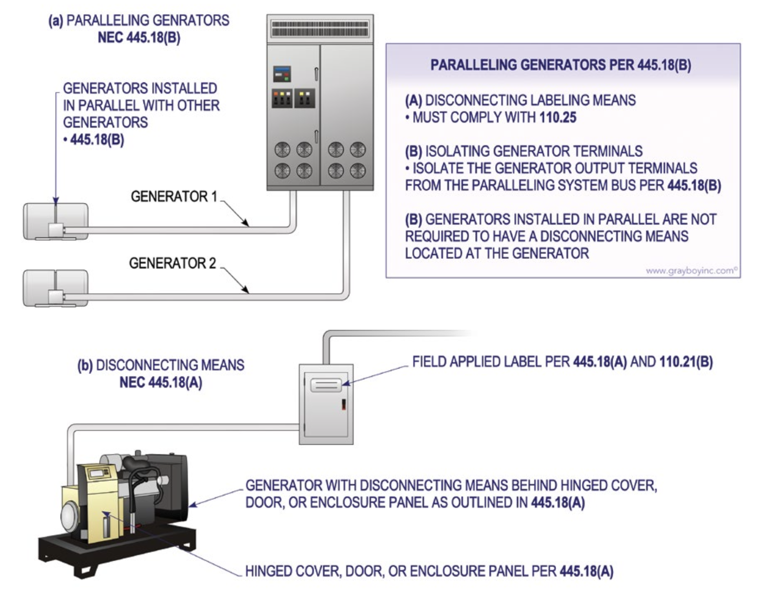
Figure 1

Leviton Solution
Powerswitch® curve top safety disconnect switches with Inform™ technology provides local and remote monitoring

  • Curve top design pushes water and debris towards the side of the device and leaves less area for buildup
  • How does Inform work?
    Sensors are embedded into Leviton devices to monitor device health. Data from sensors can be viewed locally or remotely via Wi-Fi or Modbus RTU
  • Local monitoring — Green LEDs on the cover provide a visual indication that the device is operating under normal conditions, flash red if there is a failure, or flash yellow if there is a buildup of liquid inside of the enclosure that may lead to a potential failure
  • Remote monitoring — includes data like liquid accumulation, enclosure temperature and humidity, line- and load-side voltage values, ground continuity, and more. Access this data 24/7 and get notified of any abnormal operating conditions via the Inform™ app (mobile or laptop) or your existing automation system.